Our Location
1103A Tianhui Building, Yeqin 1st Road, Longcheng Street, Shenzhen, Guangdong, China
1103A Tianhui Building, Yeqin 1st Road, Longcheng Street, Shenzhen, Guangdong, China
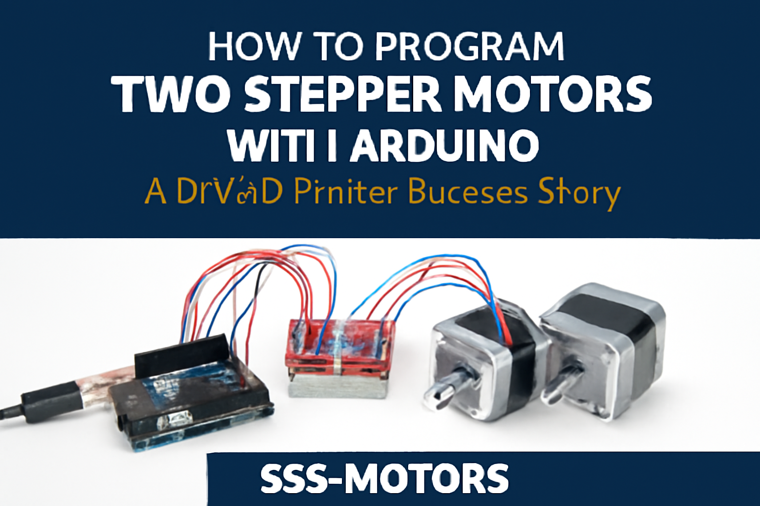
Stepper motors are an essential component for precision movement in CNC machines, robots, and 3D printers. If you’re an electronics enthusiast looking to integrate stepper motors into your Arduino project, you’ve come to the right place. In this blog, we’ll walk you through how to program two stepper motors using Arduino to control a DIY 3D printer. From understanding the components to wiring the motors and writing the Arduino code, this guide covers everything you need to know.
Meet Miguel, a passionate DIYer from Brazil who set out to build his own 3D printer from scratch. After assembling the mechanical frame, Miguel needed to control the X and Y axes using two stepper motors. Unfortunately, when using an Arduino Uno, the motors would jitter and occasionally lose steps, which resulted in inaccurate prints.
Miguel reached out for help, and we provided a solution that ensured smooth and precise movement for his 3D printer.
After analyzing Miguel’s setup, we identified the issue: the low-power stepper drivers he was using weren’t providing enough current to power the motors. To fix this, we recommended upgrading to the A4988 Stepper Motor Driver. This driver simplifies the control of stepper motors and provides the necessary current for strong, precise movement.
With the A4988 drivers, Miguel could control both motors simultaneously with more accuracy. Here’s a breakdown of the components and wiring we used.
The A4988 Stepper Motor Driver acts as an interface between the low-power Arduino and the high-power stepper motors. Here’s how you connect the components:
Once the wiring is complete, you’ll need the Arduino code to control the stepper motors. Here’s a simple code that moves both motors in sync. We use digitalWrite() to generate pulses for each motor’s STEP pin, while the DIR pins control the direction.
<!-- Pins for Stepper Motor 1 (X-Axis) -->
#define STEP1 2
#define DIR1 4

<!-- Pins for Stepper Motor 2 (Y-Axis) -->
#define STEP2 3
#define DIR2 5

void setup() {
  // Set all pins as Outputs
  pinMode(STEP1, OUTPUT);
  pinMode(DIR1, OUTPUT);
  pinMode(STEP2, OUTPUT);
  pinMode(DIR2, OUTPUT);
}

void loop() {
  // Set directions
  digitalWrite(DIR1, HIGH); // Motor 1 moves forward
  digitalWrite(DIR2, LOW);  // Motor 2 moves reverse

  // Create 200 steps (one revolution for a 200-step motor)
  for (int i = 0; i < 200; i++) {
    digitalWrite(STEP1, HIGH);
    digitalWrite(STEP2, HIGH);
    delayMicroseconds(500); // Controls speed
    digitalWrite(STEP1, LOW);
    digitalWrite(STEP2, LOW);
    delayMicroseconds(500);
  }
  delay(1000); // Wait a second
}
This simple code allows you to move both motors simultaneously in sync, one forward and the other in reverse.
Are you working on a DIY 3D printer or other stepper motor project? Our team can help! We offer high-quality NEMA 17 stepper motors, A4988 drivers, and complete motor kits for your needs. We also provide expert technical support to ensure your project is a success.
Contact us today for program two stepper motor with arduino and custom solutions and let us help you bring your ideas to life with the right stepper motor technology.