Our Location
1103A Tianhui Building, Yeqin 1st Road, Longcheng Street, Shenzhen, Guangdong, China
1103A Tianhui Building, Yeqin 1st Road, Longcheng Street, Shenzhen, Guangdong, China
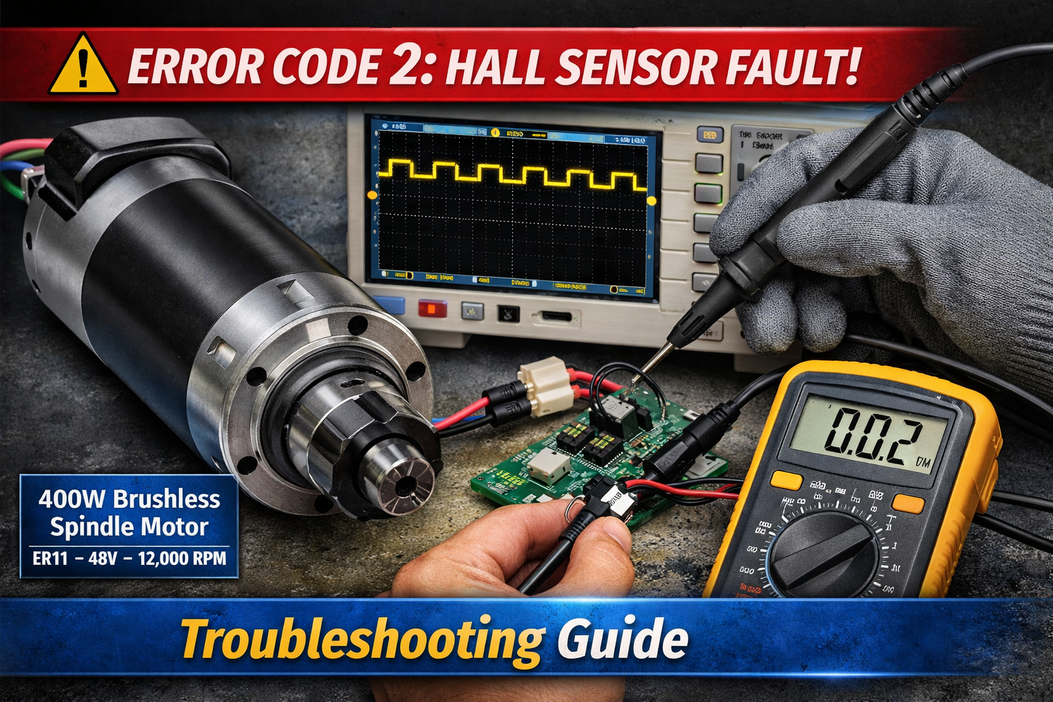
A spindle motor Hall alert (Error Code 2) is one of the most common faults reported on
brushless spindle motors used in CNC machines. The error may appear suddenly even after weeks of stable operation and usually indicates unstable Hall sensor feedback rather than a driver failure.
In this real troubleshooting case from a CNC user in Poland, we diagnosed a
400W ER11 brushless spindle motor Hall error step-by-step and confirmed the exact root cause using cross-driver testing and controlled startup analysis.
A spindle motor Hall sensor error (Error Code 2) means the driver cannot detect stable rotor position signals from the internal Hall sensors. The most common causes include Hall PCB degradation, wiring instability, connector looseness, or signal interference rather than stator winding failure.
A spindle motor Hall alert indicates that the driver cannot detect stable rotor position signals from the Hall sensors inside the brushless spindle motor.
Hall sensors provide rotor position feedback during startup and low-speed commutation.
Without reliable Hall transitions, the driver cannot synchronize current switching correctly.
Short answer: Yes — if the driver supports sensorless operation.
Sensorless control estimates rotor position using back-EMF instead of Hall feedback signals.
For a deeper explanation of how back-EMF commutation works in brushless motors, see this technical reference from
Texas Instruments BLDC Motor Control Application Report
.
Hall sensors are widely used for rotor position detection in industrial BLDC systems.
You can review the working principle in this engineering overview from
Analog Devices Hall-Effect Sensor Application Guide
.
The customer tested the spindle using a WS55-220 driver in sensorless mode by disconnecting the Hall connector.
The motor started successfully but showed noticeable temperature rise around 6,000 RPM.
| Operating Mode | Performance Result |
|---|---|
| Startup from zero speed | Reliable only with Hall sensors |
| Low-speed torque stability | Higher with Hall sensors |
| Mid-speed efficiency | Reduced in sensorless mode |
| Thermal behaviour | Higher temperature in sensorless mode |
Yes — intermittent startup success is one of the earliest indicators of unstable spindle motor Hall sensor transitions.
Drivers rely on accurate Hall edge detection during initial commutation.
If signal edges become weak or delayed, Error Code 2 Hall alerts appear intermittently.
The customer measured:
| Voltage | Measured Speed |
|---|---|
| 5V | 12,000 RPM |
| 3.33V | 8,000 RPM |
| 2.5V | 6,000 RPM |
These measurements confirm linear analog speed control behaviour.
Speed ≈ Voltage × 2400
The spindle produced the same Hall alert on a second known-good driver.
This confirmed the issue was located inside the motor assembly.
A second spindle operated normally on the same driver.
The driver hardware was therefore excluded as the root cause.
Successful sensorless operation confirmed stator windings, bearings, and power stage remained healthy.
Only the Hall feedback system remained suspect.
Successful startup during slow acceleration strongly suggested weak Hall transitions rather than complete sensor failure.
After installing a replacement Hall PCB supplied by our factory, the spindle returned to normal operation immediately.
The spindle was tested across multiple speeds during CNC machining operation for several hours without alarms.
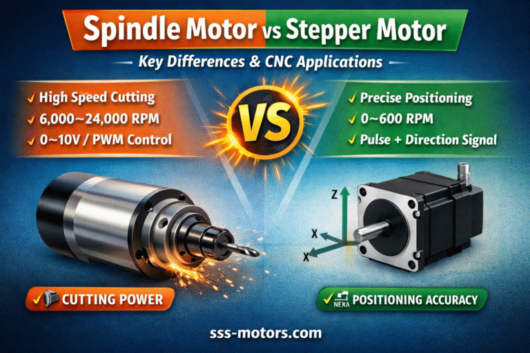
If you are selecting the best motion architecture for CNC applications, these technical comparisons help determine whether your spindle system matches your positioning strategy:
| Symptom | Possible Cause |
|---|---|
| Error Code 2 during startup | Hall signal transition instability |
| Motor starts only with slow acceleration | Weak Hall edge detection |
| Runs normally in sensorless mode | Hall PCB degradation |
| Random alarm after several weeks | Connector vibration or aging Hall sensors |
The most common causes include unstable Hall signal transitions, wiring issues, connector looseness, electrical noise, or aging Hall sensors inside the spindle motor.
Sensorless mode is possible but reduces low-speed stability and increases temperature rise. Hall feedback is recommended for CNC machining applications.
Yes. If the spindle starts only during slow acceleration, Hall edge detection instability is likely already present.
Cross-testing with another driver or another spindle quickly isolates the source of the Hall alert.
Replacing the complete Hall PCB assembly is normally faster and more reliable.